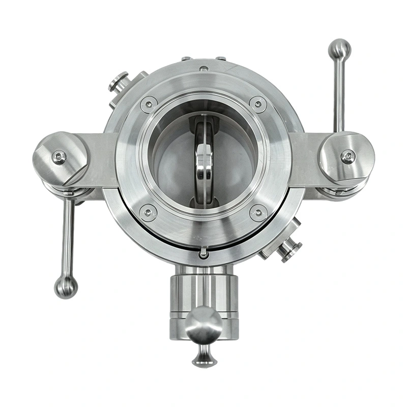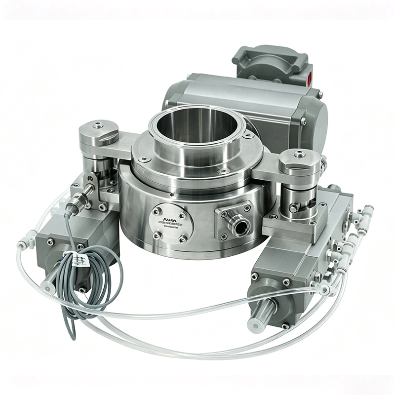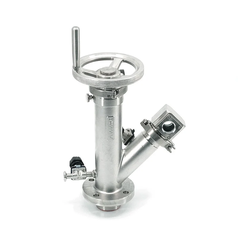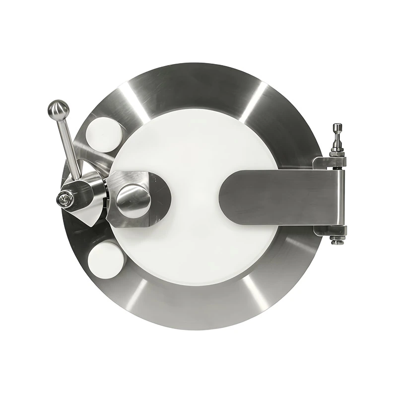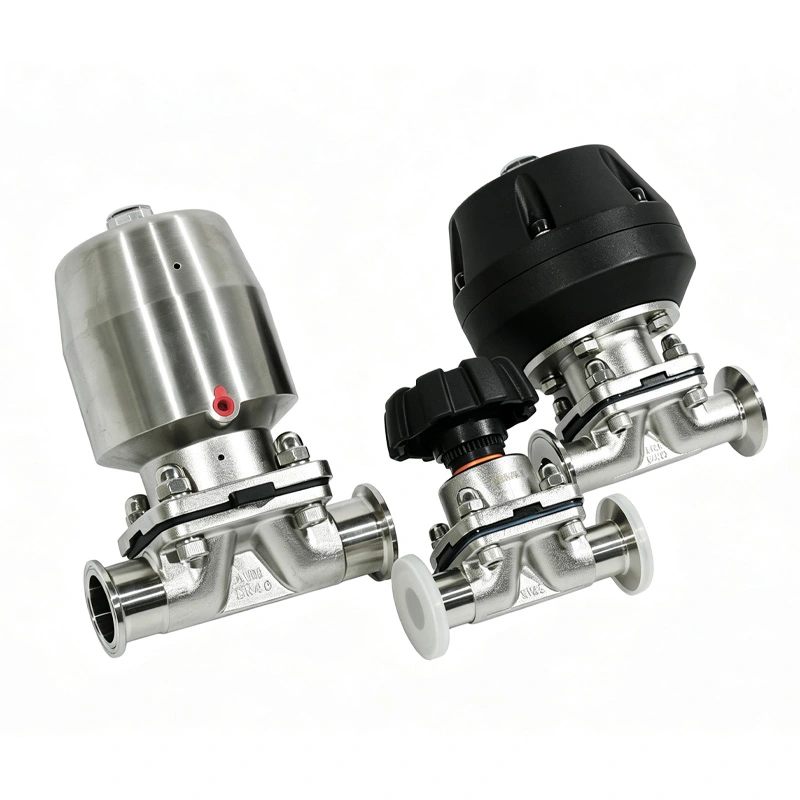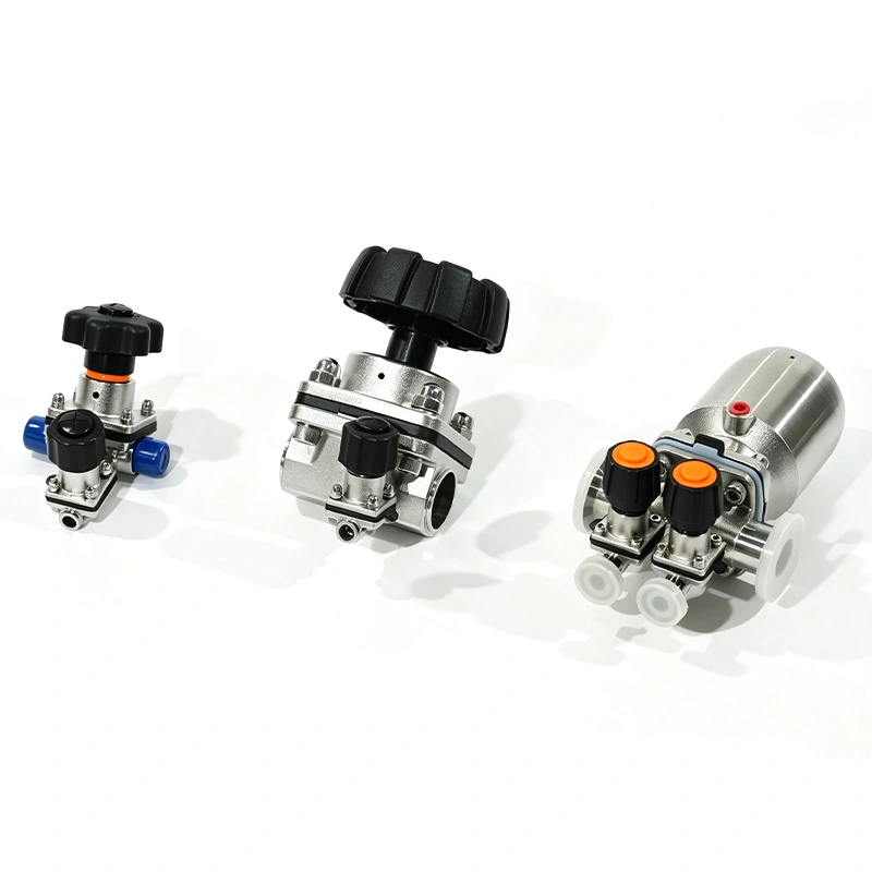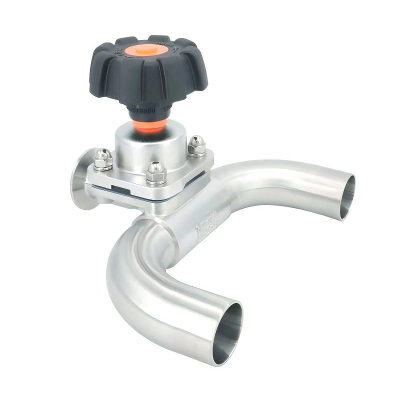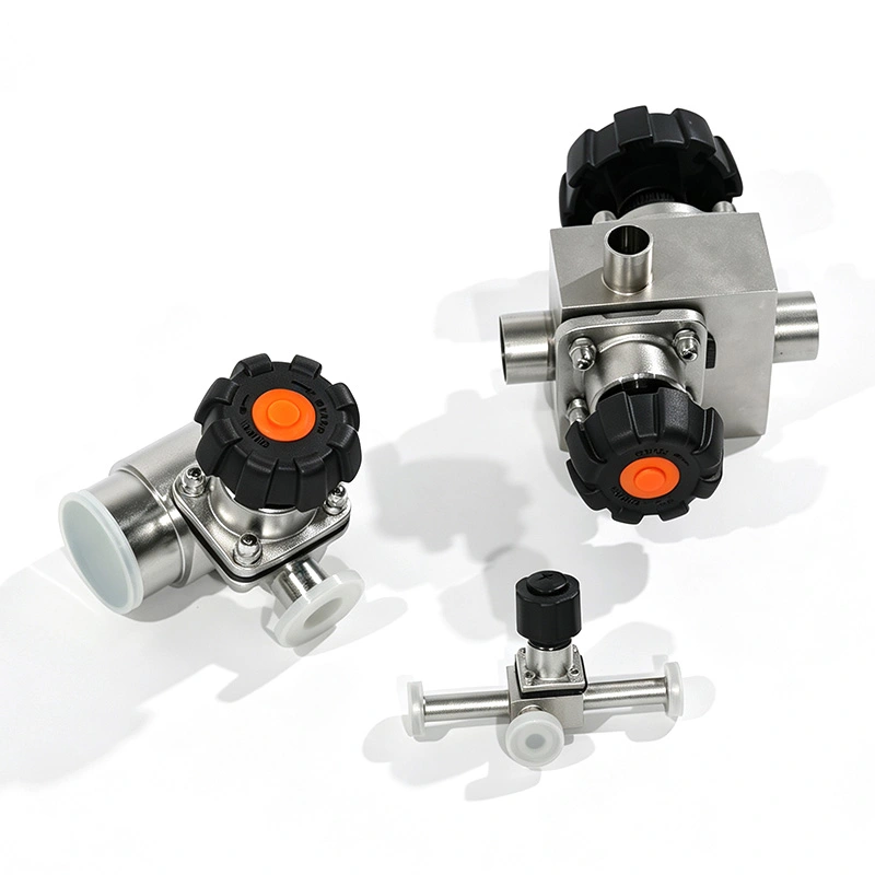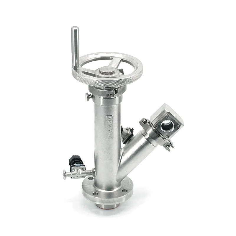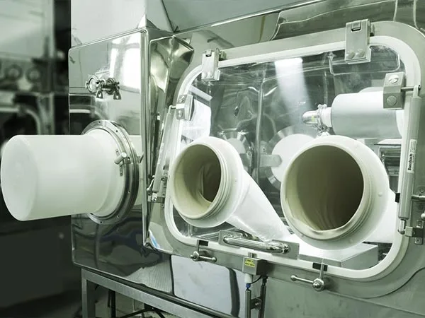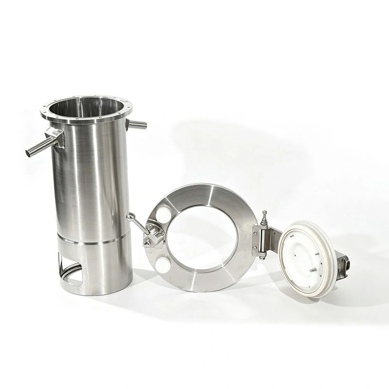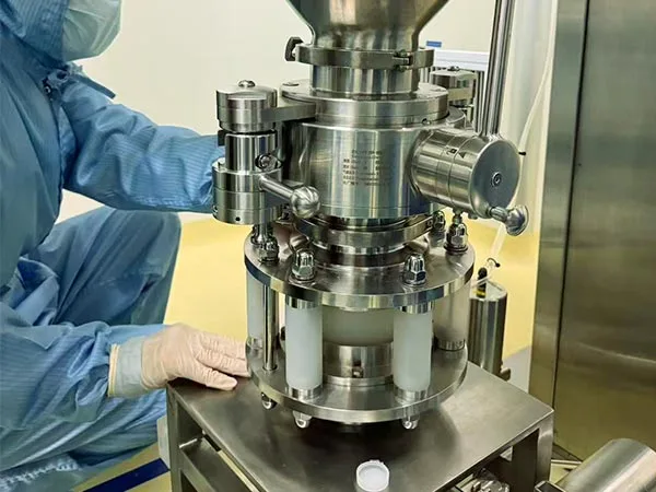
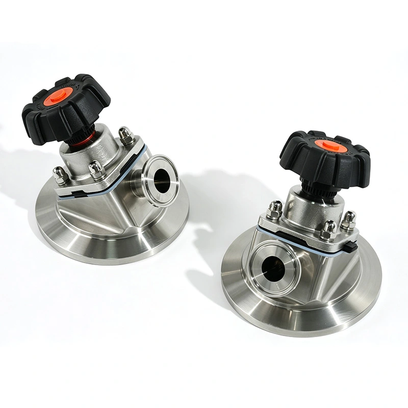
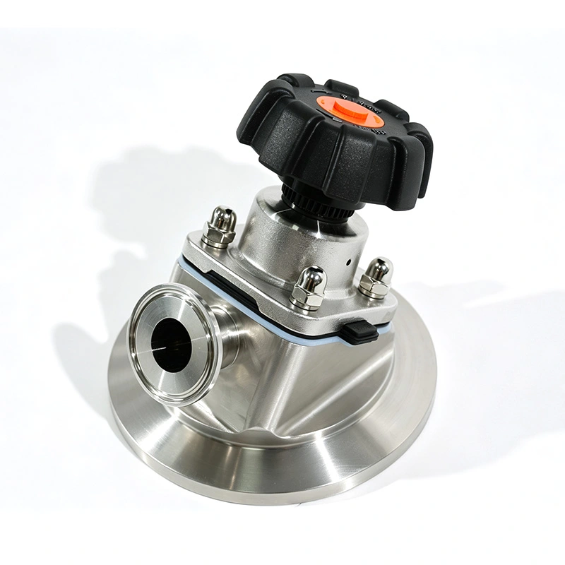
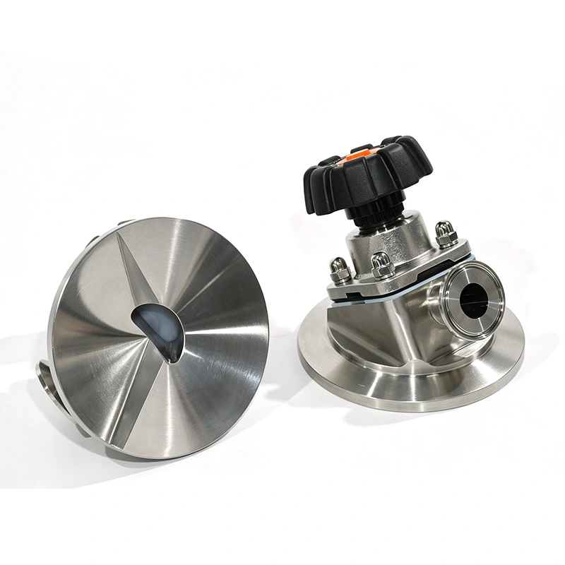
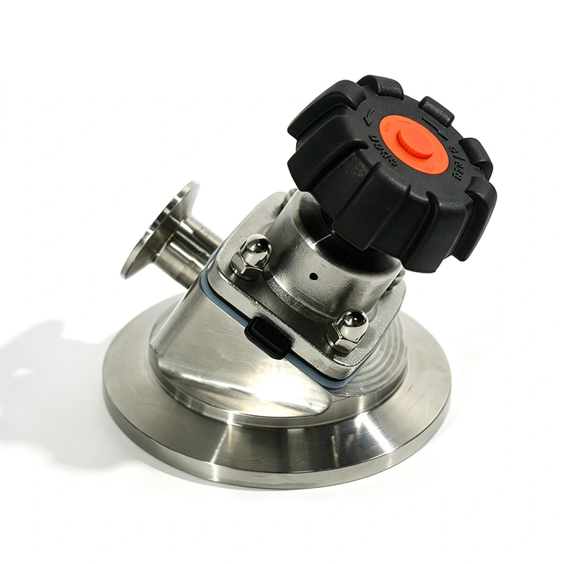
AVM Sanitary Tank Bottom Diaphragm Valve is designed for process vessels where drainage, product recovery and hygienic isolation are important. The valve is installed directly at the lowest point of the tank, with a bottom-seat structure that follows the vessel geometry to reduce dead legs and residual material.
The diaphragm separates the process medium from the stem and operating components, while the smooth SS316L flow path supports sanitary processing and routine CIP/SIP procedures. It is suitable for pharmaceutical, biopharmaceutical, food, dairy, purified water and other high-purity liquid applications.
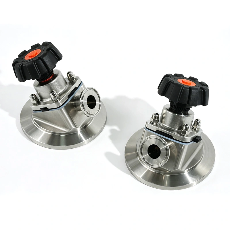
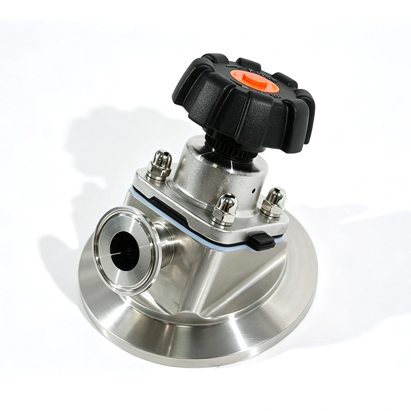
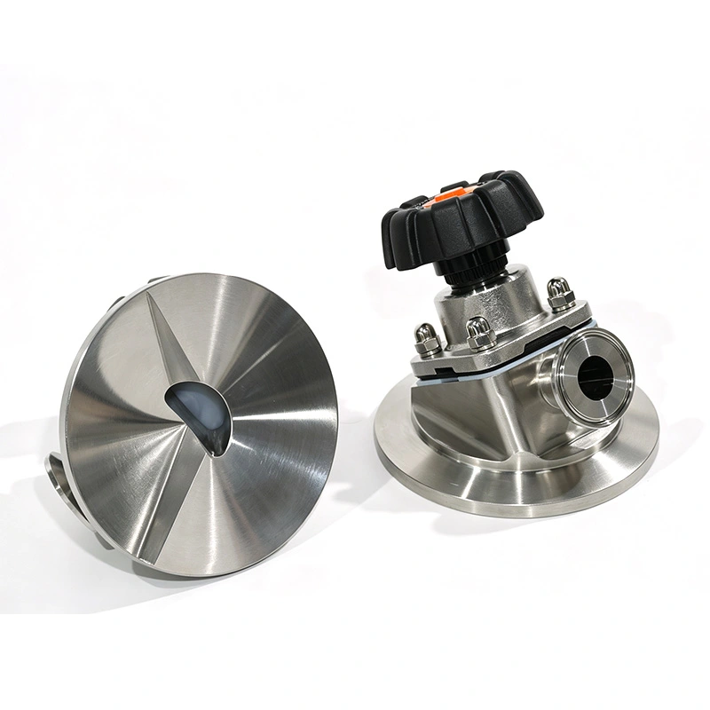
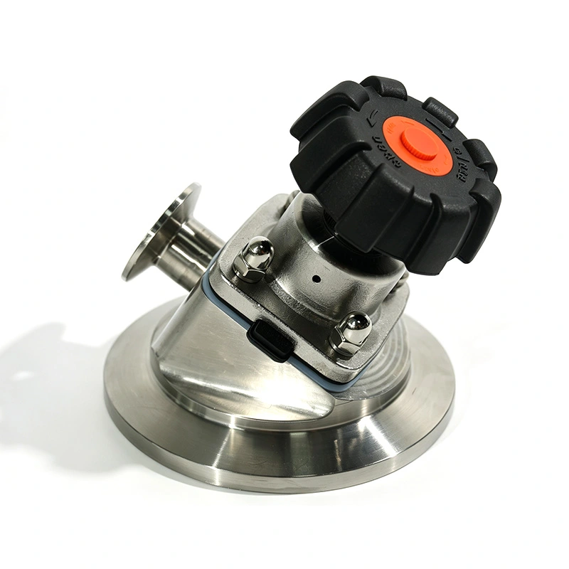
Traditional tank outlet arrangements may leave liquid or process residue in the connection area after discharge. AVM uses a bottom-mounted valve structure to reduce the space between the vessel outlet and valve seat.
The valve seat follows the bottom geometry of the process vessel, creating a more direct discharge path. This helps reduce retained liquid, simplify post-batch cleaning and improve product recovery.
The design is particularly useful for vessels handling high-value liquids, sterile products or materials that require frequent batch changeover.
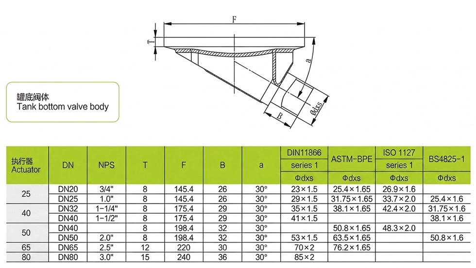
The flexible diaphragm provides both flow control and isolation between the process medium and the valve operating mechanism.
The process fluid does not directly contact the stem, actuator or other operating components. This reduces the risk of external leakage and helps maintain the cleanliness of the process side.
During closing, the diaphragm moves toward the valve seat and forms a seal around the flow opening. During opening, it moves away from the seat to provide a clear path for liquid discharge.
The diaphragm structure is suitable for process lines that require regular opening and closing, including vessel discharge, batch transfer and cleaning operations.
Hygienic valve design is important when the same vessel is used for multiple production batches. Product-contact parts are manufactured from sanitary stainless steel and finished to Ra ≤0.4 μm.
The reduced dead-leg structure helps limit areas where liquid or product can remain after discharge. The valve also supports CIP and SIP cleaning configurations, depending on the process system.
This combination can reduce manual cleaning work and make cleaning procedures easier to verify in regulated production environments.
Used on fermentation vessels, preparation tanks, API equipment and sterile process vessels where complete drainage and hygienic isolation are required.
Suitable for purified water, Water for Injection (WFI) and other high-purity liquid systems requiring sanitary bottom discharge.
Used for mixing, storage and processing vessels handling milk, beverages, liquid ingredients and other hygienic process media.
Can be installed on bioreactors and other biotechnology equipment where process cleanliness and reliable drainage are important.
Suitable for selected chemical and specialty-fluid applications requiring corrosion-resistant materials and controlled isolation.
| Parameter | Specification |
| Valve Type | Sanitary Tank Bottom Diaphragm Valve |
| Size Range | DN10 – DN100 |
| Body Material | SS316L (Product Contact Parts), SS304 (Non-contact Parts) |
| Seal Material | EPDM, PTFE, FDA-Compliant Materials |
| Surface Finish | Ra ≤ 0.4 μm (Product Contact Surface) |
| Working Pressure | -0.1 MPa to +0.15 MPa |
| Working Temperature | -20°C to +150°C |
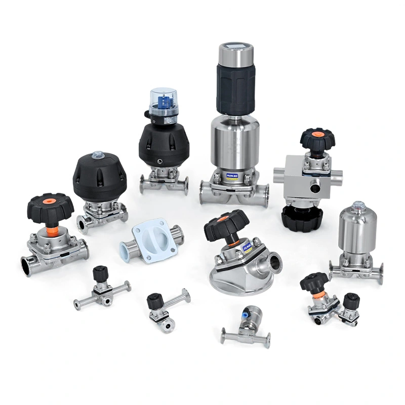
| Operation | Manual / Pneumatic Actuator |
| Connection Type | Tri-Clamp, Weld, Flange |
| Connection Standard | ASME BPE, DIN, ISO, 3A |
SS316L is used for product-contact components to provide corrosion resistance and compatibility with many pharmaceutical and high-purity process fluids. SS304 is available for non-contact components.
The diaphragm can be configured with EPDM, PTFE and other FDA-compliant materials according to the process medium, temperature and cleaning conditions. Material selection should be confirmed according to the actual application.
The valve is installed at the lowest point of the process vessel so that the outlet is aligned with the vessel drainage direction. Proper installation helps the bottom-seat structure perform as intended and reduces residual liquid in the outlet area.
For new vessels, the valve can be incorporated into the tank design during fabrication. For existing equipment, connection dimensions, vessel geometry, welding requirements and available installation space should be checked before retrofit.
A pharmaceutical manufacturer used a conventional outlet valve on a fermentation vessel and found that residual liquid remained around the tank outlet after discharge. The remaining material increased cleaning time during batch changeover and required additional manual inspection.
The customer replaced the existing outlet arrangement with an AVM Sanitary Tank Bottom Diaphragm Valve. The bottom-mounted structure provided a more direct drainage path, while the diaphragm design isolated the process medium from the operating mechanism. According to the customer's production feedback, residual liquid was reduced and CIP cleaning became more consistent.
Routine maintenance should focus on the diaphragm, valve seat, product-contact surfaces and connection points. Operators should inspect the diaphragm for deformation, cracking or other visible damage according to the plant's maintenance schedule.
The valve should be cleaned using procedures and media compatible with the selected diaphragm material. Before returning the valve to service, check the shut-off condition and confirm that the connection remains properly sealed. Replacement intervals depend on operating frequency, process medium, temperature and cleaning conditions.
It is a diaphragm valve installed directly at the bottom outlet of a process vessel. Its structure is designed to support drainage while reducing dead legs and product retention between the tank and valve.
Bottom installation provides a shorter and more direct discharge path. It can help reduce residual liquid and material accumulation around the vessel outlet.
Product-contact parts use SS316L, while SS304 can be used for non-contact components. Diaphragm options include EPDM and PTFE, with FDA-compliant materials available for applicable applications.
Yes. The hygienic structure supports CIP and SIP configurations when the valve, diaphragm material and process system are specified for the required cleaning conditions.
Yes. The valve can be used in purified water and WFI systems when the material, surface finish, connection and installation configuration meet the project requirements.
Address
No. 373 Oufan Road, Dongtou District, Wenzhou City, Zhejiang Province, China
Tel