
AVM has developed a new SBV passive valve cleaning stand designed for cleaning the passive valve in a split butterfly valve (SBV) system. This 4-inch unit integrates a pneumatic lifting assembly and a cleaning ball, providing a 450 mm lifting stroke and an adjustable operating speed of 20–50 mm/s. Its defined requirements for load capacity, air supply, cleaning flow, pressure, and drainage give engineering teams a practical basis for evaluating the equipment within an approved valve-cleaning procedure.
For pharmaceutical, chemical, and other process equipment projects, selecting a cleaning solution involves more than checking the nominal connection size. Valve compatibility, installation clearance, available utilities, cleaning media, and waste handling all need to be considered before the equipment is integrated into an existing or new process.
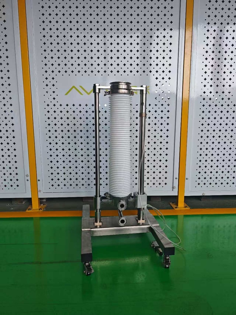
Front view of AVM's newly developed passive valve cleaning stand.
The SBV passive valve cleaning stand is designed for a specific function: supporting the cleaning of the passive valve in a split butterfly valve arrangement. It is cleaning equipment for the valve assembly, not a replacement for the transfer valve itself. According to the supplied operation manual, the product is identified as the Passive Valve Clean System (4 inch), with model and drawing reference QXQ-322-4''-00.
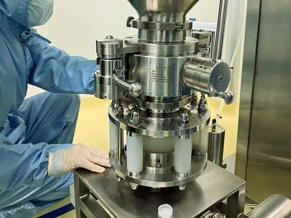
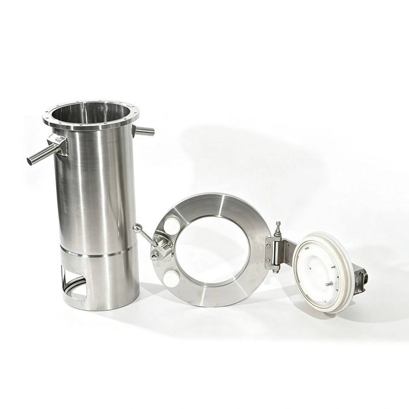
The product photographs show a vertical structure with twin supports, a central corrugated section, connection points, and a wheeled base. The manual also identifies a lifting assembly and cleaning ball that must move freely before operation. These features provide a starting point for engineering teams assessing the equipment's layout and integration requirements.
By bringing the lifting mechanism and cleaning connections into one equipment arrangement, the stand provides defined mechanical and operating parameters for developing an appropriate cleaning procedure. The final process must still be established and approved for the specific valve, residue, and installation conditions.
The manual lists a 4-inch ferrule as the process connection reference. However, a nominal 4-inch connection does not automatically guarantee compatibility with every passive valve. Buyers should verify the actual mating interface, connection orientation, and surrounding installation dimensions against the approved project drawings before ordering or installation.
The unit features a 450 mm lifting stroke and an adjustable operating speed of 20–50 mm/s. The specified air supply pressure is 5 bar, and the maximum permitted load is 200 kg. These parameters help engineers evaluate the available travel, installation clearance, pneumatic utilities, and intended operating load during equipment selection.
Installation planning should account for the entire lifting path, including the space required by connected piping and surrounding equipment. The base must be positioned on a stable, level, adequately supported surface, and all process connections should align without being forced into place. The wheeled base should not be treated as a substitute for the support or securing measures required by the approved installation and operating instructions.
One important pneumatic requirement is that both air inlets must connect to a single common 5/2-way solenoid valve. The operation manual specifically identifies this arrangement. Separate valves should not be substituted unless the configuration has been formally reviewed and approved.
Before operation, the installation team should verify the air supply and perform a controlled test of the lifting movement. Details such as tubing dimensions, air quality, solenoid voltage, port assignments, and flow-control settings should be confirmed using the final pneumatic schematic and approved equipment documentation.
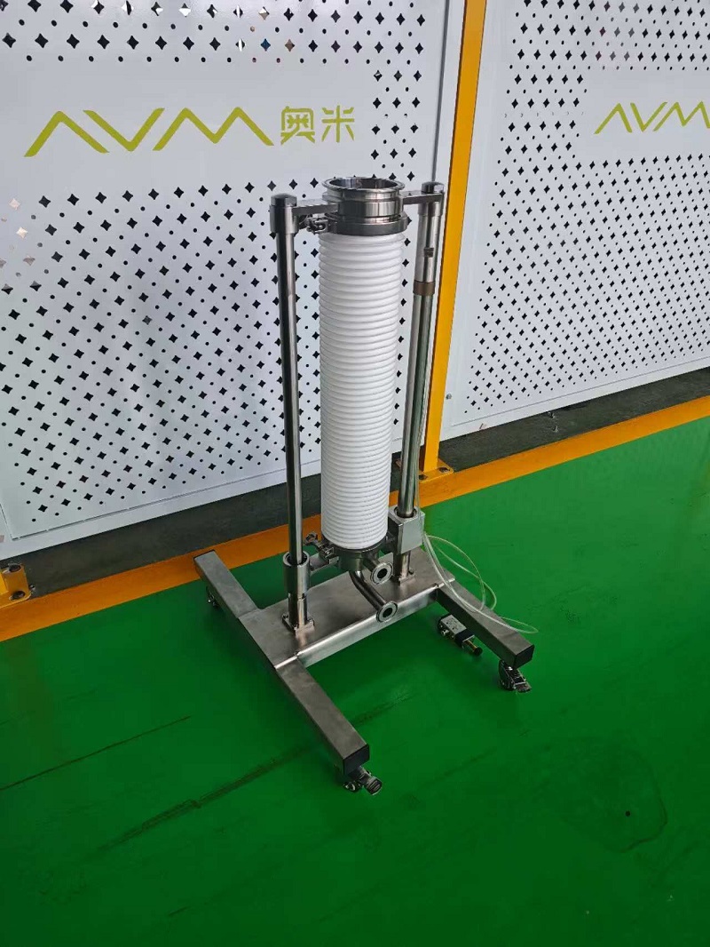
Angled view showing the stand's vertical structure and connection arrangement.
The operation manual specifies a cleaning radius of 0.8 m, a reference cleaning flow rate of 5 m³/h, and a cleaning pressure range of 2–4 bar. These values help buyers assess the available cleaning supply and the proposed equipment arrangement. They should be reviewed together with the cleaning-ball position, connected geometry, and drainage configuration.
Specified operating parameters should not be confused with independently validated cleaning performance. The stated cleaning radius does not, by itself, demonstrate that every surface within a particular installation will receive adequate cleaning. Similarly, the reference flow rate should not be interpreted as a universal cleaning recipe. Actual operating conditions must be established for the installed valve, cleaning medium, residue, and approved process.
| Technical Parameter | Manual Specification | What Buyers Should Verify |
|---|---|---|
| Process connection | 4-inch ferrule | Confirm the mating interface, dimensions, and orientation. |
| Maximum load | 200 kg maximum | Check the actual load and required support arrangement. |
| Air supply pressure | 5 bar | Verify the available pneumatic supply before operation. |
| Operating speed | 20–50 mm/s, adjustable | Set and verify movement within the specified range. |
| Lifting stroke | 450 mm | Allow sufficient clearance for the full travel. |
| Cleaning radius | 0.8 m | Evaluate cleaning-ball positioning and installed geometry. |
| Reference cleaning flow | 5 m³/h | Establish the appropriate flow for the actual process. |
| Cleaning pressure | 2–4 bar | Define and monitor the approved operating pressure. |
| Pneumatic control | One common 5/2-way solenoid valve for both air inlets | Confirm the connections against the approved pneumatic schematic. |
Cleaning media also require application-specific assessment. Before operation, confirm that the selected medium, temperature, and concentration are suitable for the valve, equipment materials, and intended cleaning purpose. The outlet must be connected to an appropriate drain or recovery system. Pressure, flow, lifting movement, and drainage should be monitored throughout the approved cleaning procedure.
For procurement teams, these requirements help establish a more complete equipment specification. Cleaning utilities, drainage arrangements, and operating procedures should be reviewed alongside the stand rather than left until after installation.
The stand supports a cleaning workflow involving equipment preparation, positioning, controlled cleaning flow, and safe shutdown. The following stages provide a general planning overview only. Actual operation must follow the manufacturer's instructions and the site's approved procedures.
Before use, inspect the base, supports, lifting path, tubing, and fittings. Confirm that the intended load does not exceed 200 kg and that the air supply meets the specified 5 bar requirement. Check the process and cleaning connections, confirm that the outlet is routed to the approved drain or recovery system, and verify the suitability of the cleaning medium before introducing flow.
Operate the common 5/2-way solenoid valve according to the approved procedure and observe the lifting movement. The assembly should move smoothly, with the operating speed maintained within the specified 20–50 mm/s range. Position the equipment as required by the approved cleaning arrangement, then apply the defined cleaning flow and maintain pressure within the specified 2–4 bar range. Monitor movement, pressure, flow, and drainage during the process.
Stop the operation immediately if movement becomes blocked, uneven, or otherwise abnormal. After cleaning, return the assembly to the designated safe position, isolate the relevant supplies, and drain the cleaning medium in accordance with site procedures. Fully depressurize the pneumatic circuit before maintenance or disconnection. Personnel must remain clear of the lifting mechanism, cleaning ball, and connected piping while the equipment is operating.
A productive equipment inquiry starts with the actual passive valve and the proposed cleaning arrangement, rather than the nominal connection size alone. Providing interface details, installation drawings, and utility requirements helps engineering teams assess compatibility and identify any additional documentation needed before commissioning.
Valve interface: Confirm the mating connection and orientation against the 4-inch ferrule reference and the approved project drawing.
Installation space and support: Check the full 450 mm lifting travel, nearby piping, base support, and expected load.
Pneumatic utilities: Verify the 5 bar air supply and the common 5/2-way solenoid-valve arrangement. Confirm the remaining circuit details against the approved schematic.
Cleaning conditions: Define the cleaning medium, temperature, concentration, flow rate, and pressure for the installed process.
Drainage and recovery: Identify the appropriate discharge route and establish procedures for isolation and draining.
Cleaning acceptance criteria: Determine how cleaning results will be evaluated for the specific valve, residue, and process requirements.
The supplied manual does not specify material grades, surface-finish values, seal compatibility, temperature limits, or a validated cleaning cycle. It also does not establish automatic CIP capability or sterilization performance. If any of these are essential project requirements, they should be confirmed through application engineering and supporting documentation rather than inferred from product photographs or headline specifications.
Reliable operation depends on routine inspection as well as correct installation. AVM's manual calls for a general inspection before each use, including checks of the supports, moving path, tubing, and fittings. Daily or per-shift checks should address air pressure, leakage, movement, and abnormal noise. Additional inspections at site-defined intervals should cover fasteners, alignment, tube routing, and the condition of the cleaning ball.
Troubleshooting should follow a systematic approach. If the lifting assembly does not move, check the air supply, common solenoid valve, and both tube connections. If cleaning results are unsatisfactory, review the cleaning-ball position, flow rate, pressure, and process conditions. Do not assume that the stand alone determines cleaning effectiveness. Damaged components should be replaced with approved parts, and maintenance must only be performed after the equipment has been isolated and depressurized.
AVM's new 4-inch passive valve cleaning stand provides a defined lifting and cleaning arrangement for SBV applications. Its documented stroke, adjustable speed range, load limit, and utility requirements give engineering and procurement teams a practical basis for assessing integration into an existing or planned process.
Contact AVM to discuss your SBV passive valve cleaning application. Share your valve interface, installation layout, cleaning requirements, and available utilities to help determine whether the system meets your project needs before installation and commissioning.